1. Setting the I2C Address
The way modules are addressed changed during the development.
The current method uses 8 pins in the backplane of the rack to do the addressing. It is automatically used if the control module is in its intended slot.
The legacy method is not advisable to use. It uses a switch on the module which defined its address. This method is still used if the control module is not in its intended slot.
Depending on the method, follow either step 1a or 1b below.
1a. Current method
 Make sure that the control module is in the right slot according to the picture above. The module gets addressed depending on which slot in the rack it is in. Do not use the slot labeled with NC.
Warning: Make sure that the switches of the switch array (labelled A0, A1, A2 on the board) are all off. If that is not the case, it will interfere with the automatic addressing.
1b. Legacy method Setting the I2C Address
On the card, there is a switch array controlling three bits (labelled A0, A1, A2 on the board). The switch array is displayed on the image below for the Dac4D module card.
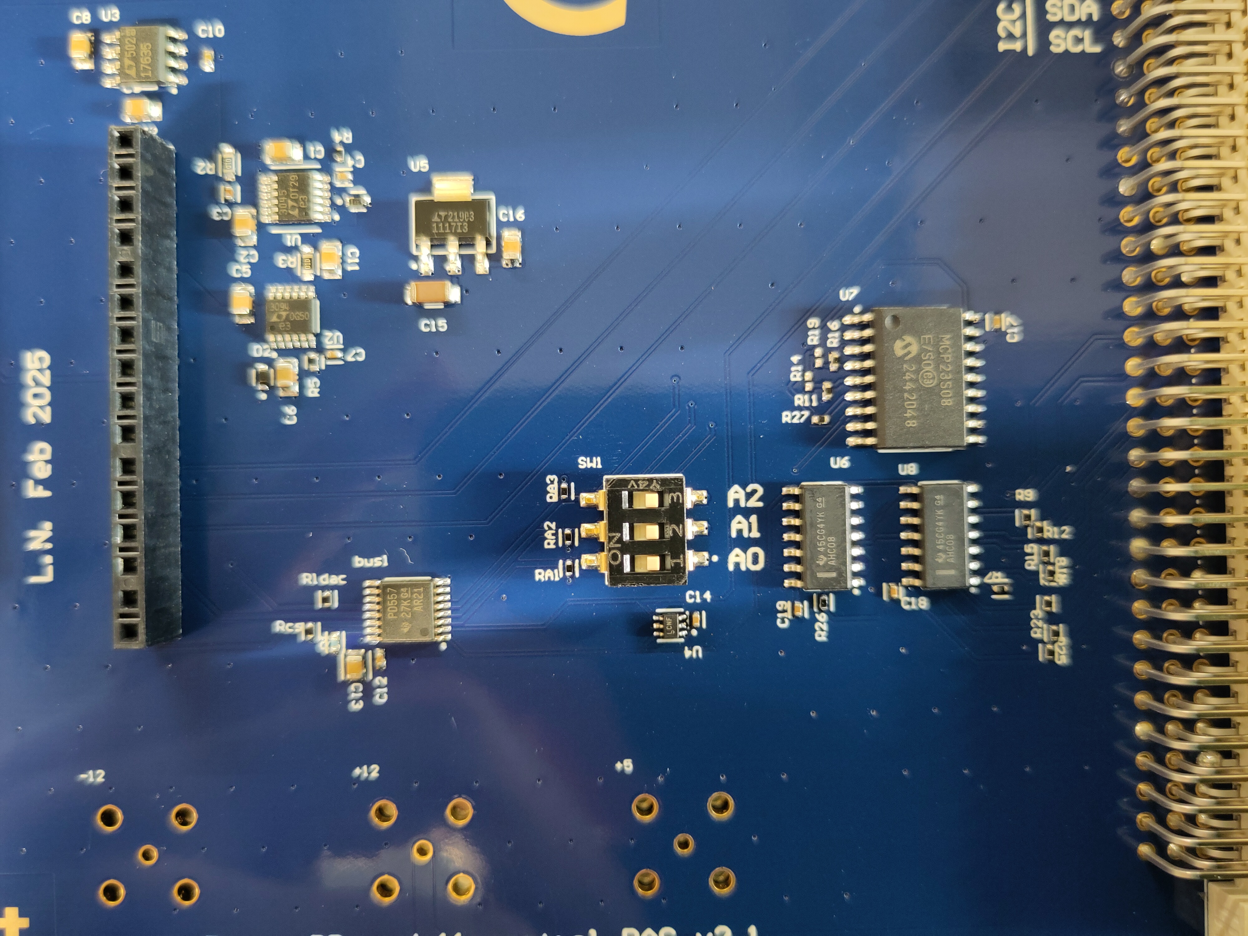 This switch array defines the address of the module. Each card in a rack must have another address (except for the control module, which does not have an address). If there are already cards installed in the rack, check their address switch array and choose an unused address configuration for the switch. A0 is the least significant bit and A2 the most significant bit.
Examples A0 = ON, A1 = OFF and A2 = OFF corresponds to an address 1. A0 = ON, A1 = OFF and A2 = ON corresponds to 0b101 = 5.
2. Inserting the Card
Please make sure that the rack is switched off and disconnect it from the mains power supply. Then insert the card in a free slots. The plastic rails guiding the card might not be in the correct position for the connector at the back to mate to the rack. You can take them out an insert them at the correct location.
3. Check if the Control Module Recognizes the Card
Now, power on the rack, connect the control module to the computer via USB and open the Arduino IDE (or any other software allowing to monitor serial communication) and connect to the board. If you use Arduino IDE, go to Tools>Serial Monitor . Send the command reset and check the reply. It should contain the line
I2C device found at address XXX !where XXXis the value of the address you set.
4. Initializing the Module
This step depends on the way the rack is going to be used. Either, the initialization can be done in the frontend or directly via serial communication.
Option 1: Via Serial Communication
With the serial monitor still open from Step 3, send the command
SETDEV [address] [device_type]
with the address set in Step 1 and device_type is either DAC4D, DAC4D, DAC4ETH, DAC16D
Example:
When device_type was DAC4D, then the control module answers with
deviceType: 1
DAC4D created
LTC268X initialization error 0
+ok
if there is no error. TODO: add answers for other modules.
Now, you can send module-specific commands via serial communication.
Option 2: In the Frontend
With the development environment
If you have the development environment set up, start the UI by following Browser Development. If you have the DBay software from https://github.com/bkorzh/dbay/releases installed, you can start the GUI this way
In the UI, click on the menu bar (three horizontal lines) and select Add a module. Then, in the newly opened box, select the module slot (it is the address value +1). Then select the module type and click Add Module.